Casting defects cost foundries millions annually in scrap, rework, and customer returns. Yet many defects share similar appearances — porosity can mimic shrinkage, and inclusions can be mistaken for gas holes. Effective troubleshooting requires a systematic approach: identify the defect visually, trace it to root cause, then implement targeted corrective action.
This practical guide focuses on the three most common defect families — porosity, shrinkage, and inclusions — providing visual characteristics, root cause analysis, and proven corrective measures for iron and steel castings.
Defect Family #1: Porosity (Gas-Related)
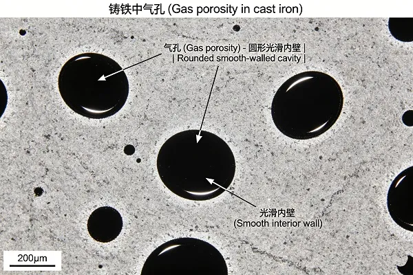
Porosity refers to voids caused by gas evolution during solidification. Gases (hydrogen, nitrogen, carbon monoxide, steam) become less soluble as metal solidifies and form bubbles that become trapped.
Visual Identification
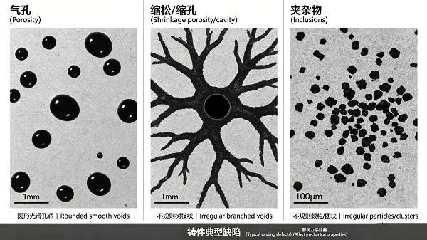
- Appearance: Smooth-walled, rounded or spherical cavities
- Surface: Often shiny or slightly oxidized interior surfaces
- Distribution: Usually scattered throughout the casting or concentrated in hot spots
- Size: Can range from microscopic pinholes to large visible cavities
Common Root Causes
| Gas Type | Source | Typical Appearance | Primary Corrective Action |
|---|---|---|---|
| Hydrogen (H₂) | Wet charge materials, moisture in refractory, oil-contaminated scrap, humid environment | Fine pinholes throughout section | Dry charge materials thoroughly, preheat furnace, control humidity |
| Nitrogen (N₂) | Excess nitrided ferroalloys, air entrainment, high nitrogen in coke | Small, round pinholes, often in clusters | Reduce nitrogen-bearing alloys, improve melt covering, use low-N recarburizers |
| Carbon monoxide (CO) | Incomplete deoxidation (steel), high oxygen content, reaction between carbon and oxygen | Subsurface blowholes, often elongated | Improve deoxidation practice, add strong deoxidizers (Al, SiCa), control oxygen activity |
Corrective Actions Summary
- For hydrogen porosity: Dry all charge materials, preheat ladles and tools, avoid organic contaminants, use gas flushing with inert gas (Ar or N₂) for steel.
- For nitrogen porosity (gray/ductile iron): Reduce nitrogen-bearing recarburizers, switch to low-N carbon raiser, avoid high-N ferroalloys.
- For CO porosity (steel): Ensure thorough deoxidation — adequate aluminum or SiMn addition, verify with oxygen sensor, consider calcium treatment.
- General gas porosity: Improve melt covering to prevent air contact, control pouring temperature (avoid excessive superheat), ensure proper gating design for smooth metal flow.
Defect Family #2: Shrinkage (Solidification Contraction)
Shrinkage defects occur when liquid metal contracts during solidification and insufficient feed metal is available to compensate. Unlike porosity, shrinkage cavities have irregular, jagged surfaces with exposed dendrites.
Visual Identification
- Appearance: Irregular, angular, or branched cavities
- Surface: Rough, dendritic, crystalline appearance (not smooth)
- Distribution: Concentrated in last-to-solidify regions — heavy sections, beneath risers, at thermal centers
- Types: Open shrinkage (visible on casting surface) and microshrinkage (internal, detected by radiography or machining)

Common Root Causes
- Inadequate risering: Risers too small, improperly placed, or freeze off before feeding is complete
- Poor directional solidification: Hot spots isolated from feed paths, no thermal gradient toward risers
- Low inoculation (cast iron): Poor graphite expansion reduces self-feeding capacity
- Excessive superheat: Higher pouring temperatures increase total shrinkage volume
- Incorrect alloy composition: Carbon equivalent too low (gray iron), or excessive carbide-promoting elements
Corrective Actions Summary
- Riser design: Increase riser size, add insulating sleeves or exothermic materials, reposition risers to feed heavy sections.
- Gating modification: Use chills to promote directional solidification, add feeding aids, redesign to eliminate isolated hot spots.
- Inoculation (gray/ductile iron): Increase inoculation level or switch to barium-bearing inoculant (FeSiBa) to enhance graphite expansion feeding. Ba levels of 2-4% are particularly effective for shrinkage reduction.
- Pouring temperature: Reduce superheat to minimum practical level for the casting section.
- Composition adjustment: For gray iron, increase carbon equivalent to 3.9–4.1%; for ductile iron, ensure proper magnesium level and carbon equivalent.
Defect Family #3: Inclusions (Sand, Slag, Dross)
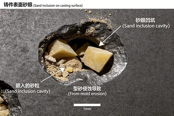
Inclusions are foreign materials trapped in the casting — sand from mold erosion, slag from melt handling, or dross (oxides) from surface reactions.
Visual Identification
- Sand inclusions: Granular, light-colored particles (brown, gray, or white), often clustered near surfaces or in corners
- Slag inclusions: Glassy, irregular, dark or light-colored masses, often with rounded edges, usually near the top of the casting
- Dross/oxide inclusions: Thin, filmy, wrinkled surface layers (often dark or metallic), or internal folded films
Common Root Causes
| Inclusion Type | Source | Primary Corrective Action |
|---|---|---|
| Sand inclusions | Mold/core erosion from turbulent metal flow, low mold strength, improper ramming, high pouring temperature | Reduce turbulence (gating design), increase mold hardness, use lower pouring temperature, apply mold coatings |
| Slag inclusions | Poor slag skimming, insufficient slag cover in ladle, reoxidation, ladle carryover, inadequate slag trapping in gating | Improve skimming practice, use slag-reducing ladle covers, install slag traps in gating system, use ceramic foam filters |
| Dross/oxide inclusions | Melt exposure to air, insufficient deoxidation (steel), low inoculation (iron), turbulent filling breaking surface films | Improve melt covering, add strong deoxidizers (Al, CaSi for steel; FeSi for iron), use stream inoculation, reduce pouring turbulence |
Corrective Actions Summary
- Sand inclusions: Optimize gating for non-turbulent filling (avoid free fall, use tapered runners), increase mold hardness, apply wash or coating, reduce pouring temperature if possible.
- Slag inclusions: Use ceramic foam filters in gating system (10–30 ppi), design slag traps (runner extension, vortex traps), improve ladle skimming, use slag coagulants.
- Dross (iron castings): Increase inoculation (especially with FeSiCa or FeSiBa), improve melt covering, reduce pouring temperature, use stream inoculation to prevent reoxidation.
- Dross (steel castings): Ensure complete deoxidation (Al or SiMn + Ca treatment), pour under inert gas cover, use exothermic/hot topping compounds.
Rapid Visual Reference Table
Use this quick-reference table to distinguish between defect types on the shop floor:
| Characteristic | Gas Porosity | Shrinkage | Inclusion (Sand/Slag) |
|---|---|---|---|
| Cavity shape | Rounded, spherical, smooth | Irregular, angular, branched | Variable — granular or glassy masses |
| Cavity surface | Smooth, shiny, oxidized | Rough, dendritic, crystalline | Not applicable (solid particles) |
| Distribution | Scattered, uniform | Concentrated in hot spots | Near surfaces or in gating areas |
| Metallography | Rounded voids with no dendrites | Jagged voids with exposed dendrites | Particles with different composition |
| Common fix | Dry materials, deoxidize | Risers, chills, inoculation | Filters, skimming, mold quality |
Systematic Troubleshooting Workflow
When faced with a defect, follow this sequence:
- Examine the defect visually — Smooth and rounded? → Gas. Jagged and dendritic? → Shrinkage. Embedded particles? → Inclusion.
- Locate the defect — Top of casting? → Slag or shrinkage. Bottom or thin sections? → Gas porosity. Heavy sections? → Shrinkage.
- Review process parameters — Pouring temperature, melt chemistry, inoculation/deoxidation practice, gating design.
- Conduct confirmatory tests — Thermal analysis (undercooling), chill test, radiography, or SEM/EDS for inclusion identification.
- Implement corrective action — Change one variable at a time, verify results with a test casting run.
Case Example: Porosity vs. Shrinkage Misdiagnosis
A foundry producing valve bodies experienced 15% rejection for internal cavities visible after machining. Initial diagnosis assumed gas porosity; operators increased deoxidation and dried materials without improvement. Re-examination of radiographs showed cavities were irregular with dendritic surfaces — classic shrinkage, not gas. Corrective action: added chills to heavy sections and increased riser size by 30%. Rejection rate dropped to 3%. The lesson: correct identification is the first and most critical step in troubleshooting.
Effective defect troubleshooting transforms reactive scrap management into proactive quality control. By systematically identifying whether a defect is porosity, shrinkage, or inclusion — and tracing it to root cause — foundries can implement targeted corrective actions that reduce scrap, improve casting integrity, and lower costs. Bright Alloys supports foundries with high-quality ferrosilicon inoculants, deoxidation alloys (Al, SiMn, CaSi), and filtration solutions to help eliminate these common casting defects.